Tekla Structural Designer 2019 Service Pack 3
2019
Tekla Structural Designer
Link to download
Environment
Not environment-specific
This release will upgrade your Tekla Structural Designer installation to version number 19.0.3.44 and should be installed to ensure optimum function of the program. It includes a number of enhancements and issue resolutions as detailed below.
If you are upgrading from a version earlier than the latest release 2019 SP2 (version 19.0.2.33) you can find details of requirements, enhancements and fixes for all previous releases in Tekla User Assistance (TUA) and Tekla Downloads via the links below:
- Tekla User Assistance Main version release notes
- Tekla User Assistance Service Pack release notes
- Tekla Downloads
Licensing & Installation
- Licensing:
- No new license is required for this version.
- License Server Version - for Server licenses, it is always our recommendation that you are running the latest version of the Tekla Structural License Service on your license server. Please see System Requirements for specific version details.
- Installation - this service pack requires Tekla Structural Designer 2019 to be installed.
- Previous Versions and file compatibility - Files from all previous versions can be opened in this release however note that, once saved, they may not open in an older version. If you wish to retain this option we therefore recommend using the File > Save As… option to save a new version of the file and retain the original.
Highlights
General & Modeling
Sub Structures Enhancements
Sub Structures are saved user-defined selection groups of any objects which can be of any size and mix of object types, materials etc. They can be viewed in isolation and used as filters for many areas of program operation. Using Sub Structures has multiple productivity benefits throughout the Structural Designer workflow, from model organization and editing through to results review, design and output. Their creation, review and editing is now made even easier. For illustration see this video Sub Structure enhancements:
- Sub Structures and Sub Structure Groups can now be both created and edited via the Structure Tree context menu:
- The main Sub Structures or Sub Structure Groups folder are now always visible even when no Sub Structures have been created. New Tooltips for these explain what Sub Structures are. Right-click on either of these to access the Create option, or right-click on an existing Sub Structure or Group for the Edit option. In both cases the view then switches automatically to the Review View in the Sub Structure Review/Update mode, which now uses the Ghosted Structure view to display the objects not in the Sub Structure.
- An option to Rename a selected Sub Structure is also added to the context menu.
Image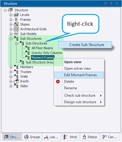
- Sub structures can also be created and edited directly from the scene; simply make a graphical selection of objects then select the new Add To Sub Structure… command from the scene context menu (right-click to open this). An additional dialog then opens listing any Existing Sub Structures as shown in the picture below. You can choose to add the current selection to one of these, or create a new Sub Structure. Additionally, all selected objects are listed on the left of the dialog with on/off check boxes, allowing further filtering of the selection.
- When in a View of a Sub Structure, the scene context menu also includes a Remove from Sub Structure option applicable to the current selection in the view.
Image
Slab Modeling Enhancements
By popular request, slab items can now easily be moved to another existing slab group or into a new group where the engineer wishes to change the arrangement of slab type/ properties in their model.
- A new drop-list is added to the Slab general properties which both lists existing slabs and includes a New Slab option - simply select slab item(s) and choose an existing or new group to make the desired edits.
Image
Selection Enhancements
Individual spans of continuous beams and stacks of continuous columns can now be graphically selected, in the same way as individual wall panels in previous versions, both by individual mouse-click and selection window, facilitating more rapid model review and editing.
- As shown in the picture below, it is now possible to easily select - for review/ edit via the Properties Window - only the stacks in a particular level or levels for multiple columns with a single selection window operation.
- The same applies to selection of only specific spans of multiple continuous beams where, for example, you may wish to change the section only for these spans.
- Note that selection lines and right-to-left windows will still select the entire intersected beam/column.
Image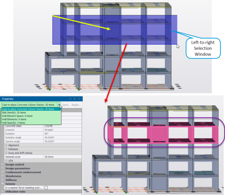
- Note that selection lines and right-to-left windows will still select the entire intersected beam/column.
- Note that:
- When entire beams/ columns are selected - by whatever method - the Properties Window drop-down will list them both as single entities - with all general and span/stack properties - and as a collection of multiple spans/stacks - with only span/stack properties. See the picture below illustrating this.
- For Steel Column Lifts (length between splices which may contain multiple stacks), it is not possible to edit the section unless all stacks in the lift are selected.
- It is not possible to delete a single stack/span - delete still deletes the entire member.
Image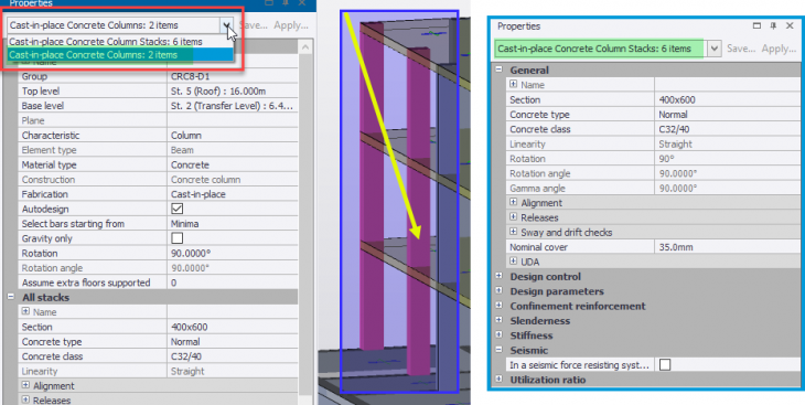
Output
Reporting Enhancements - General
The Export to Excel option has been added to both the Analyze and Review Tabular Data views. Using this, any of the Tabular Reports in these views can be sent to an Excel spreadsheet, facilitating further processing and easy sharing of model, analysis and design data with other parties.
- When the tabular report is configured as you require, simply click the new Excel Export button at the right of the ribbon to automatically send it to a new Excel spreadsheet - the resulting data is listed in separate, headed columns and cells just as it appears in Review Data.
Image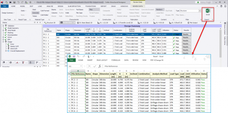
Piles
[TSD-802, 1459, 3621]1 - in accordance with customer requests, the reporting of concrete pile results for both piled mats and pile caps is significantly enhanced. For illustration see this video Pile Reporting Enhancements.
- The Review Data > Design Summary for piles is expanded and enhanced with the following information:
- Pile X and Y location coordinates, Inclined Yes/No, Governing Combination and Analysis Method, Load Type, Pile Load and capacity.
- As detailed above, this comprehensive tabular report can now be exported directly to Excel for easy sharing with third parties such as piling contractors.
- Foundation Layout Drawing - Any/all data from the enhanced tabulated Pile Design Summary can also be added as an automated table to the Foundation Layout Drawing.
- By default the table includes the following information; Pile Reference, Name, X & Y Location Coordinates, Load and Limit.
- Additional columns can be added as required via a new control dialog in Drawing Settings > Options > Foundations > Foundation Layout as shown in the picture below.
Image Image
Image
Enhancements & Fixes
Performance
- [TSD-1682, 1684, 3545]1 - Analysis & Design time and RAM Usage - both analysis and the combined analysis and design process (run by any of the “Design…” buttons on the Design ribbon) may require significant time and occupy a significant amount of computer RAM (termed “RAM usage”) to both perform all the calculations involved and store their results. The time and RAM required depends on a number of factors including the model size, the number of design combinations and the computer operating system and specification (see Tekla Structural Designer 2019 system requirements for specification recommendations). The internal processes involved in analysis and design have been streamlined and optimized in a number of areas for this release in an effort to reduce both time and RAM usage during analysis and design to yield potentially significant performance improvements.
- [TSD-1588]1 - 1 D Element results - an example of this is the internal processes for the calculation and storage of 1D element results which have been entirely revamped. In particular it is expected this should reduce file sizes, file save/opening times and peak RAM demand following the analysis and design processes, with associated analysis speed improvements.
- Please note that:
- Potential performance improvements are model and computer dependent.
- Development of performance improvements is an ongoing process and remains a key focus for future releases.
- [TSD-4102]1 - Interactive design of Concrete walls - a new option to "Suspend Checking" has been added to the Interactive Design dialog, as shown below, so that several edits can be made before re-initiating checks. When not checked the program continues to operate as before: checks are made after every edit. For large structures with many combinations this checking takes time which can be frustrating if you want to make several changes. When checked on, the button highlights in red making it clear checking is now suspended. All checks are then carried out and results updated for any changes made when the option is unchecked.
Image
- [TSD-4244]1 - Properties Window - when working with selections of many objects especially in larger models, the speed of populating the Properties Window with the selection data is significantly enhanced to the extent of being almost instant where previously a number of seconds could be required.
- [TSD-3700]1 - an issue introduced in the first release of version 2019 causing intermittent freezing of the program is fixed in this release.
- A number of additional fixes which are not detailed explicitly here are also made to improve general performance and stability. An example of this is the issue listed directly below here:
- [TSD-4094]1 - Concrete Columns - Editing - a crash would occur when a concrete column top level was changed to a level where a connection of concrete beams existed and a beam support point was within the perimeter of the column section area. This is fixed in this release.
General & Modeling
- Concrete Cores:
- [TSD-3163]1 - Create & Modify - a new object type Filter option is added to the Core Create and Modify modes to assist with these processes in more complex models. This is active when the Assisted method is disabled. For Create, the filter can be set so that only Columns or Walls can be selected for inclusion in a new core, while for Modify the selection can also be restricted to Beams.
Image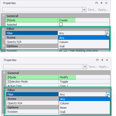
- [TSD-3199]1 - Validation - a new validation routine has been introduced for concrete cores which checks for the analytical connection of core members at levels. The intersection of the solid shape of objects does not mean they are necessarily analytically connected. Analytical connection is not required for cores, but engineers may wish to see cases where the group of objects does not have inherent core - i.e. fully analytically connected - behaviour along its height if this is their assumption/ intention.
- In the case of uncoupled core members (columns or walls) existing at a level, the new check will issue a Validation warning. The warning does not apply if, at all levels of the core, columns, walls and beams (of coupling beam construction type) form a continuous and interconnected section.
- [TSD-3163]1 - Create & Modify - a new object type Filter option is added to the Core Create and Modify modes to assist with these processes in more complex models. This is active when the Assisted method is disabled. For Create, the filter can be set so that only Columns or Walls can be selected for inclusion in a new core, while for Modify the selection can also be restricted to Beams.
- [TSD-3794]1 - Ghosted Structure View - this feature, which assists with visualizing the location of parts of the structure viewed in isolation - such as Sub Structures - which was added in the 2019 Service Pack 2 release, is now enabled for the Member View (for more on the feature see the 2019 Service Pack 2 Release Notes and this video Ghosted Structure view ).
Loading
- [TSD-4128]1 - Concrete Walls with Openings - in previous versions, when area loads were applied to concrete walls with openings, load would be displayed graphically within the opening. The decomposable loads calculated on the same basis would consequently be greater than reactions (which correctly deducted the load in the openings). This imbalance would show up as an error in the Project Workspace Loading tree. In this release the behaviour for this circumstance is now like that for area loads on slabs with openings - the area load is cut back around the opening and its area excluded from the Load Summary checks to correct the issue.
- Note that if you wish the opening area(s) to be loaded, place a Wind wall over the concrete wall(s) and instead apply the area load to this NOT to the concrete wall.
- Optionally you can set the Wind wall to decompose to members, which will result in area load being applied to the solid area of the wall and line loads to the opening edges appropriate to the Wind wall’s span direction - see the 2019 Service Pack 2 Release Notes for more on this.
- [TSD-4533]1 - an erroneous Decomposition Status Warning which was issued in this circumstance in previous releases is no longer issued.
Image
- [TSD-4533]1 - an erroneous Decomposition Status Warning which was issued in this circumstance in previous releases is no longer issued.
- Wind Walls:
- [TSD-4496, 4532]1 - An issue affecting wind load decomposition for wind panels overlaying concrete walls with openings is corrected in this release. For certain models, if the wind panels were set to decompose to nodes, an analysis error would be reported in the process window and the analysis process would not complete. If the panels were switched to decompose to members the analysis would complete, although a decomposition warning would be issued in relation to the portion of wind load applied over the concrete wall opening. This warning was unnecessary and could be ignored. In this release the analysis now completes in this circumstance without warnings or errors irrespective of whether the wind panels are set to decompose to nodes or members.
- [TSD-4353]1 - An issue introduced in the 2019 SP2 release which caused a validation error for walls spanning to mid-pier concrete walls is fixed in this release.
- [TSD-3209]1 - Parapets - for the special case of Parapet Wind wall panels spanning horizontally to Parapet Posts supported by columns, the panel load is decomposed as a lateral point load and point moment (which would be produced by a UDL on the post) to the top of the supporting column. In some circumstances the engineer may wish only the lateral load but not a moment to be applied. This is now catered for in this release as follows:
- A new option “Ignore local moments from lateral loading” is added to Wind wall properties which is available only when the “Is a parapet wall” setting is checked on. When the new setting is checked on, only a lateral point load is applied to the top of a supporting column. No moment is applied. Note that:
- The special decomposition of point loads - with or without a point moment - to supporting columns only occurs when all the following are true; the wind panel spans horizontally to parapet posts, the “Is a parapet wall” setting is checked on for the wall panel, the parapet post is supported by a column.
- In both the following cases a UDL will be decomposed to the members onto which the parapet wind panel spans;
- The member supporting the parapet post is NOT a column.
- The member onto which the parapet wind panel spans is not a parapet post (e.g. is an extended column or vertical beam)
- This new setting is not checked on by default either in existing nor new models, so the default behaviour is as previously.
Image
- A new option “Ignore local moments from lateral loading” is added to Wind wall properties which is available only when the “Is a parapet wall” setting is checked on. When the new setting is checked on, only a lateral point load is applied to the top of a supporting column. No moment is applied. Note that:
- [TSD-4183]1 - Load Combinations Generator - Eurocode Head Code - the generation of EQU Combinations is updated with a new Dead + Wind combination. Specific factors in accordance with the National Annex of the Head Code Country are included where appropriate (including Finland and Sweden).
Analysis & Results
- [TSD-4643]1 - Load Decomposition and Analysis - an issue introduced by the load decomposition enhancements in 2019 SP2 (see the 2019 Service Pack 2 Release Notes for more on this) is fixed in this release. The issue occurred only in the following specific circumstances; models with one-way slabs spanning on to two-way slab edges in a level set to be the source of another level.
- Details - in this circumstance, the line load decomposed to the two-way slab edge would be incorrectly applied twice to the duplicate floor(s). It would generally be clear when the issue occurred, as it also prevented the processing of 1D element results for affected load cases so, for example, no 1D element results would be displayed for these in the Results View. The issue could be worked around by setting the relevant level(s) to be unique. Since results were still available for combinations including such cases however, the issue could result in members supporting any doubled loads being over designed.
Design
General
- [TSD-1571]1 - Concrete Design - Columns and Walls - Australia, Eurocode and US Head Codes - for the design of Longitudinal bars, the axial buckling load Pc of the stack/ panel is calculated (always for the Eurocode and for the slender case for Australia and US Head Codes since it is required for moment magnification calculations). When the limiting value of the buckling load (e.g. 0.75Pc for ACI 318) is exceeded by the design axial load, it is impossible to evaluate the magnified moment factor and the check has effectively failed. In this circumstance the design summary now reports this failure and design no longer proceeds to the moment resistance checks at each position. Previously, an overall fail status would correctly be assigned to stacks/panels for combinations with this issue, but a moment utilization ratio < 1.0 could be displayed in the design summary table and passing moment checks in the design details, which was confusing.
- The utilization ratio now reported in the design summary table for this failure is that of the design axial load / buckling load limit (e.g. Pu/0.75Pc for ACI 318) which thus will always be > 1.0.
- [TSD-4440]1 - Steel Design - Continuous Beams - Deflection - In the design summary the critical deflection considering all spans and all combinations is now correctly displayed. The critical deflection item for each span for each combination is also correctly marked and governs auto-design.
- Previously the results for a non-critical span could be displayed in the design summary and auto-design might not correctly select a passing section. In such a case however, the overall pass/fail status would still be correctly governed by the critical span/combination and the design details for this were correct.
Head Code Eurocode
- Foundation Design - Pad Bases:
- [TSD-4174]1 - Bearing Capacity Check - a Warning status was incorrectly displayed against the Bearing Capacity check utilization ratio (UR) when this was 0.67 < UR < 1.0. This warning is removed from this check as it is only applicable to the sliding check, for which it is correctly issued. This issue and TSD-4265 relate only to release 2019 - in which they were introduced - and subsequent releases.
- [TSD-4265]1 - Sliding Check - in conjunction with the above, while the Warning status was correctly issued for the sliding check, the warning text was not displayed so it was unclear why the warning was issued. This is reinstated, warning that the check assumes that full vertical load exists in combination with horizontal loads and to ensure combinations consider the possibility of reduced axial load.
Head Code US
- [TSD-4367]1 - Steel Joist Design - the Size Constraints > Max/Min depth settings would always revert back to the defaults of 72" and 8"respectively, and so could not be user-edited. This issue is fixed in this release.
Reports & Drawings
- [TSD-4095]1 - Concrete Beam Detail Drawing - All Head Codes - in some circumstances the lap lengths of top and bottom support bars extending into the design length (beyond the support face) were shown shorter than intended. Full tension laps are assumed in the software, so it is assumed correct lap lengths would be provided during the final detailing exercise. The lap visualisation is improved in this release.
- [TSD-4124, 4405]1 - Beam End Forces Drawing - the drawing would fail to create for levels which contained continuous steel beams. A workaround, where acceptable, was to make the beams un-continuous. This issue is fixed in this release and the drawing is correctly created.
Footnotes
1 This number is an internal reference number and can be quoted to your local Support Department should further information on an item be required.